-edible zone-
--The Story behind "Notes on the TD124" starts around 2006 or 7. It was near to that time when Art Dudley ( a well known Linnie) published his first TD124 article in the "Listening" column at Stereophile. I wasn't really looking for a TD124 but I got an email from a turntable hunter offering me a fixer-upper for ~$350 or so. (I can't remember exactly what I paid) It arrived not long after and that's how I came into possession of sn#2729. This was my first Thorens TD124. What I found with 2729 was that it was built to receive service. I documented my processes here on the site and that led to... -- Notes On The TD124
--Original post date: 05/20/2010, revisions made 05/07/2014, Then more revisions in 2022. By now, the new page mission is to expand on the owner and service manuals with examples of the various processes. (please note that new material and edits to the page are still in progress at this time)
 (hint: click on thumbnail to view image full size)
-- Above: Magazine ad scan from early in the period.
-- Above: An original neon strobe bulb. Type NE 48 or Phillips GL 1W
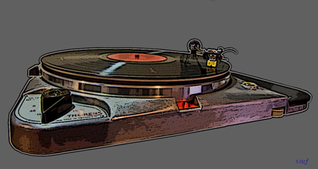
-- What it is: The TD124, it's a 4-speed belt-idler driven turntable produced in the early Stereo era.
Features:
-- Die-cast aluminum chassis
-- 4-pole 10 watt shaded pole AC
induction motor E-50
-- 9lb iron flywheel
-- 1 lb. Light aluminum
clutch-able upper platter with mat.
-- Ø 14mm hardened & ground steel
bearing shaft. Ball-thrust. Oilite Bushings.
-- Friction pads on
flywheel.
-- A simple clutch lever which - when you push it forward
- scissor-Lifts the light upper platter off the working flywheel. That
stops the record spin. ---- Then, when ready, you pull the lever back
your way to scissor-drop it back down into the working flywheel. Instant
go. Like a DJ at a radio station would use back then.
-- Operates 50
or 60hz, depending on country.
-- Operates from 100 to 250 VAC,
depending on country.
-- Neon lit Strobe
-- ± 3% Variable pitch
speed control
-- The Cast Chassis: Die-cast aluminum by Inca.
--
Casting revisions were made within the first version as noted below.
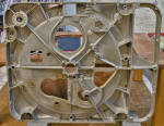
-- Below: three shots of sn#2078 An
early first version. Arm board area. Note square corner where the arm
board bed adjoins the chassis. Note also the center web / arm board bed.
 (hint: click thumbnail for full size)
-- Below: sn#27520 shows revisions in two areas of the casting; -bevel at juncture between the arm board bed and chassis, -gusset reinforcement added to center web,
-- The early version chassis have often been found to be bent in the arm board area as a result of customer handling. No doubt this prompted Thorens to make the above noted revisions to the casting. The good news is that bent arm board areas on early castings can be straightened.
-- Bearing and Platter System
-- Above image: A detailed section view of the platter and bearing
system
It's a two-piece platter system. On top is the light
aluminum clutch-operated platter. There are 6 rubber pucks located in a
circular array adhered to the flywheel beneath it. The pucks provide
friction to drive the upper platter while the flywheel is in motion. A
simple clutch lifts the upper platter up off the flywheel when the
operator pushes a lever forward. It drops the platter back down on the
working flywheel when the operator pulls the lever back.
-- Below: Control map (re-annotated) from the owner's manual
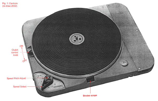
Above: an alternate section view
The Iron Flywheel:
 (click thumbnails for full size image)
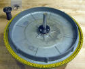
Above: iron flywheel showing traces of rust. In the beginning stages.
-- Above photos: TD124 cast iron flywheel with the bearing
disassembled from it. When stored for lengthy times in humid conditions
the iron will rust. In the above case the rust wasn't so bad. A spoonful
or two of Naval Jelly then some judiciously applied elbow grease removes
all the traces. Yet the flywheel is cast iron and iron rusts. The lesson
to be learned time and again is don't store these outdoors where they
will always rust. Keep them indoors in the home where you live and
sealed away from weather.
-- Material: Cast Iron, weight: 9
lbs. (note the light upper platter weighs 1 lb, total wt. platter
system is 10 lbs) Another note about the iron flywheels I've seen is
that all surfaces of them have been lathe turned and trued. It's
original design purpose was to produce a robust 'flywheel effect' with a
high moment of inertia at the outer rim, and thusly achieve the
wow/flutter readings they did.
-- The fit of the platter over the
bearing shaft is very close, very precise...so precise, in fact, that
you can remove the three mounting screws and remove the platter from the
bearing while it resides within the player. Then replace the platter
just as it was, re-tightening the screws just as they were, and there
would be no change in concentric run-out between flywheel and bearing.
It spins just as true every time. Unfortunately, the same can not be
said of the lighter non-magnetic (cast zinc) platter. More about that
below.
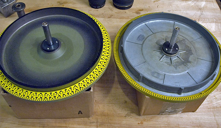
-- Above photo: side-by-side underside of the two flywheel types used on the TD124. Left: the cast-iron platter (fully machined and trued on all surfaces). Right: The cast-zinc platter from the TD135. The zinc platter uses an adapter plate to fit the TD124 bearing. Note the difference in strobe patterns. The iron platter offers a strobe pattern for each speed and at either 60 or 50 hz. The zinc platter offers a pattern for 33-1/3rd rpm at either 50 or 60 hz.
-- The Non-Magnetic Flywheel:
-- Material: Die-cast Zinc - adapted from the TD135 - part number CB
788 And also produced at the Inca foundry.
This flywheel weighs
closer to 5 lbs and will display lathe-turned surfaces only where
required for mechanical function. The main benefit of it* is that it
does not attract the magnet within moving coil phonograph cartridges. (*
as I see it)
The zinc flywheel uses an adaptor plate (spacer) in
order to get it to work with the TD124 bearing shaft and in that
chassis. It should be noted that when you remove and replace this
flywheel from its bearing, it will be needed to align the platter to the
bearing shaft when you re-assemble. If you don't you will see
significant run-out between platter and bearing - it's quite visual -
and there might be an audible wow. My solution is to do what every other
machinist would do; get out the dial indicator and align the flywheel to
the bearing while it is in the chassis. I'll add some photos of this
process anon. Otherwise the zinc platter works fine and the audible
difference in performance between that of the iron flywheel and the zinc
is not huge. Unless the idea of using a moving-coil cartridge over the
iron flywheel triggers significant mental trauma for the owner.
(kidding, just kidding, I think) Otherwise, I feel the iron platter is
the better sounding of the two. Greater flywheel effect. Slam is more
robust.
At some point Thorens management did admit that there
were one - or maybe two - cartridges that they could not recommend the
use of while playing over the original iron flywheel. According to
Joachim Bung in his book "Swiss Precision" 2nd ed. these stand-outs were
the Decca FFSS and the Neumann DST. Those two, it was decided, had
magnets within them that were just too strong to be used over the iron
flywheel. Evidently it was considered ok to use any version of the
Ortofon SPU cartridges, and those are known to have very strong magnets
within them.
From my own experience I can add that many moving
coil type cartridges do have magnets within them that will demonstrate
some downward magnetic pull while tracking the record over an iron
flywheel. This can be compensated for by adjusting vertical tracking
force to accommodate it. I have written more about that further down the
page and also have produced an additional page to illustrate one method
for making this compensation.
________________________________horizontal rule
-- The Power Unit:
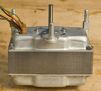 The E50, a 4-pole 10 watt shaded pole AC induction motor. It's
behavior has influence on the character of the machine. Sixty years of
experience has taught us that this, along with other parts, will need
regular maintenance. The good news is that it is built to receive
regular maintenance....and you can get the parts you'll need.
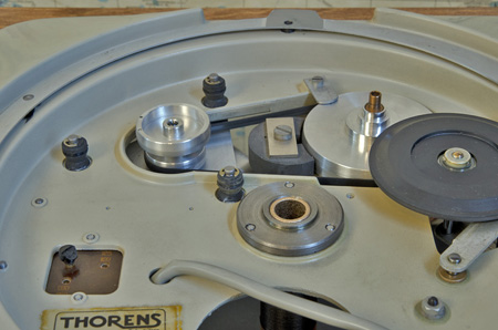
-- The E-50 drives an elastic (rubber) belt that turns a 4-speed
magnetically damped stepped pulley. The stepped pulley serves as the
capstan which turns the idler wheel that turns the inner rim of the 9lb
iron flywhee. It's a 'belt-idler' drive. The four speed range includes
16, 33-1/3rd, 45 and 78 rpm. The magnetic damping occurs via an eddy
brake which produces enough drag against the belt for a variable speed
pitch adjust system. The measured belt-drag also serves to damp motor
cogging action somewhat. The shaded pole design of the motor manages to
produce a smoother running motor, while the eddy brake dampens the flow
of power a bit further.
(note: A similar shaded pole/eddy brake
design was used on the Garrard 301 players of that era, but the Garrard
didn't use a belt.)
Eddy Brake speed pitch control: Directly beneath the stepped pulley a permeable magnetic reflector is rotated into position relative to the permanent magnet just opposite. More reflector exposure directly opposite the magnet results in greater eddy brake effect against the rotation of the stepped pulley. Less exposure results in less eddy brake effect.
1
 2
2

3
 4
4

-- Above 4 photo sequence; Photo 1 shows position of reflector to achieve negligible eddy effect. Photo 2 shows position of reflector to achieve maximum eddy effect. Photos 3 and 4 indicate the pitch control knob that is turned via your fingers to adjust this.
_____________________________________________________horizontal rule
-- It's a Four-Speed Transmission

-- Above sketch indicates point of adjustment (via F1029 shims) to align the idler wheel relative to the stepped pulley that drives it.
-- More on the motor - E50 (ME 380)
-- motor rpm: 60 hz: 1740 (average)
-- motor rpm: 50 hz 1450 (average)
-- Note: motor rpm is variable ±3% by means of the eddy brake pitch adjuster, which increases or decreases drag on the motor at the belt/stepped pulley.
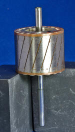
-- Measuring rotor shaft for wear
-- measuring bushing ID (used bushing)
-- measuring bushing ID (new bushing)
-- Measure coils for uniform ohms readings
-- Clean
-- Polish rotor shaft when needed - but don't reduce its size or alter its form.
-- Check the Running clearances shaft to bushing: I've
determined that a desired bushing to shaft running clearance will range
between .0008" and .0010". (inches) Less than that puts drag on the
motor at the bushings and that no amount of upper to lower bushing
alignment will alleviate that much drag.
Over the past few years
I have been taking micrometer readings for wear on E50 rotor shafts.
These are identified by the turntable serial numbers.
-- Project - SN#59805
-- Measuring the rotor shaft for form and size on chassis sn# 59805.
Short end: Ø .18660 to .18670 The .0001" of taper variation is
measurable and repeatable. Checking for roundness indicates zero
deviations.
Long end: Ø .18695 to .18685 The variation seen is
due to slight wear (.0001"). Btw, these measurements I resolve to the
nearest 10-thousandth of an inch. (While the instrument reads out to 5
decimal places.)
Differences in size between long end and short
end, I attribute to manufacturer's process variation. Manufacturers work
to within a tolerance specified within their own process control. And
now we can see an average difference between the long and and the short
end of .0003 inches. That does not surprise me (coming from the
manufacturing world myself) and likely fits within factory allowed
tolerance.
Note: for this rotor shaft I simply cleaned
the shaft ends with acetone. The result was a finish on the shaft ends
that exhibited no need for polish. Size remained the same. Nice
specimen, actually.
 Left: using the mic to check the rotor shaft diameters.
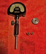 Left:
Mahr split-ball type bore gage
-- Note: About the Mahr spit-ball gage. (above image) It gets
its internal read by means of a two-point 180° contact. With this type
of gage it is possible to evaluate any irregularities in the roundness and cylindricity of the bore. To measure the bore for roundness one simply
rotates at the same length location and take the read again.
To
measure for taper, (that is any difference in diameter over the length
of the feature), one takes reads at several points along the length of
the feature. Then report all of the differences in reads found within
the feature bore.
Note also the set-ring in use for this feature
size. This is the calibrated reference in use for the read. As an
additional reference measure, once set the Mahr gage can also be checked
with the micrometer
After a bath in lacquer
thinner, the bushings are checked for cleanliness then the bores are
measured using the Mahr bore gage.
In this instance a set ring in
use has as its stated diameter .1869 inches. The set ring is used to
calibrate the Mahr gage to read zero at .1869 inches. Then reads are
taken within the bushing bores and the difference in read between the
bushing bores and set ring determine actual bushing ID size.
One
bushing measured .1876 and the other .1877 inches in diameter. Both
checked round. Same for taper. No taper and no out of roundness on the
bushings. This is better than I thought it might when I first viewed the
bushings after disassembly.
 (click
thumbnail for full size)
-- Above photo: the setup to check the new bushings for inside diameter size and form.
-- Measurements:Both of the new bushing's inside diameters measure very close to the same in size at Ø .18720 inches. There was no taper or out-of-roundness detected while measuring the bore with the Mahr Gage pictured. That reflects a deliberate and well controlled machining environment where they were produced. Meanwhile the rotor shaft diameters measured between Ø.18660 to .18695. With this information we can determine that the bushing to shaft operating clearance will be between .0006 to .0003". That is quite a bit tighter than what was measured between the old bushings and shaft ( .0008 to .0009 inches clearance)
-- Update to motor bushings being used on Sn#59805:
-- date: 2/16/2022
-- Earlier in February 2022, the owner of this TD124-II made contact with me with a complaint that his unit wasn't reaching stable speed quick enough on a cold start-up. I invited him back over here and when he came with #59805 I was able to solve the cold-start issue by replacing the too-tight "new" motor bushings with the good oem set that showed no evidence of wear and should not have been replaced in the first place. This corrected the slow warm-up issue. Now, in fact this TD124 starts from cold in the most robust manner I've seen in any E50 motor so far. The new running clearance between shaft and bushing now measures between .0008 and .0009". (That is 8 ten-thousandths of an inch.) Much finer than a human hair.
-- The previously installed "new" bushings had been fitting tighter with .0006 to .0003" running clearance. This experience has taught me that the E50 motor works better and healthier with the larger running clearance noted above, which, by the way, is still less than one thousandth of an inch. I will remember this going forward and aim for a bushing to shaft running clearance of .0008 to .0010 inches.
-- Lubrication: I'm using the Texaco ROB oil (20 wt. turbine oil) for the motor.
--#E50 motor coils: What to check
 (click thumbnail for full size image)
-- Above photo. Checking the coils for overall health on the E50 motor that came with project chassis Sn#24520.
-- The idea is - we check ohms readings on each of the coil lead ends as follows:
Coil #1:
black - yellow: 55.5 ohms
black - red: 86.2 ohms
black - green: 265.2 ohms
Coil #2
black - yellow: 53.5 ohms
black - red: 81.5 ohms
black - green: 259.7 ohms
-- It is the differences in readings between coil 1 and 2 that we are looking for. Preferably, all comparisons would be closer than a 2 ohm difference.
-- Differences in readings between coil 1 and coil 2:
black - yellow: 2 ohms
black - red: 4.7 ohms
black - green: 5.8 ohms
-- When cleaned up, assembled and run-tested the motor was very low on torque and did not carry pace at all. This I anticipated as being due to faulty motor coils. I ordered a new set of coils from Audiosilente in Rome, Italy. Turnaround was fast. I had the coils on Tuesday after placing the order on the previous Friday. Very fast turnaround. Excellent service coming out of Rome, Italy!
 (click for full size)
-- Above photo: new coils ready to go in. Old defective coils to the left.
-- Prior to assembly an ohms check was made on the new coil set from Audiosilente as follows:
-- Coil #1
black - yellow: 22.3 ohms
black - red: 70.1 ohms
black - green: 102.8 ohms
-- Coil #2
black - yellow: 22.4 ohms
black - red: 70.2 ohms
black - green: 103.2 ohms
-- The reads compared between coils #1 and #2 were within 0.4 ohms at the greatest deviation. Very close.
 (click for full size)
-- A very important E50 motor assembly step; the axial alignment between the upper and lower bushings relative to the rotor shaft.
The easiest way to accomplish a proper alignment between upper and lower bushings is by assembling the motor without firmly tightening the 4 bolts that hold the assembly together. Leave the nuts just barely loose enough to allow shifting position at both upper and lower case ends. This allows one to move one case end and the other by hand. The object is to arrive at an alignment that allows the longest spin-down time when the rotor is spun between thumb and fore-finger. Greater than 10 seconds is the goal. By hand. when this is achieved, tighten the 4 bolts and do the spin test again. You are done when the four bolts are tight (not too tight) and the spin test results in the same 10 seconds or greater spin down times. The goal is for the rotor to turn as freely as it possibly can.
-- It is critical that the spherical bushing ends are allowed to swivel as per design. Here are some mounting detail photos of the bushing installments.
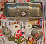
-- Above photo: looking at the motor bottom case and a typical assortment of new parts to be assembled into it.
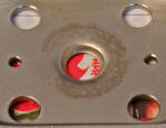 Left: close-up detail of the spherical seat.
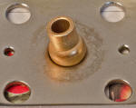 Left: The spherical base of the bushing matches into the spherical seat
of the casing, creating a swivel joint. This enables both the
upper and lower bushings to self-align at assembly. (in theory, anyway)
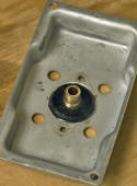


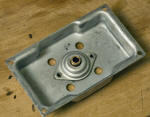


-- Above photo sequence: lower case bushing assembly.
-- Electrical

-- Above image: power voltage map for the TD124 electrical hook-up.
______________________________________________________horizontal rule
-- Stepped Pulley Bearing Design: There were two versions.
Early Version.....Below: 5 shots of the early inverted design that uses an axle fixed solidly to the chassis by means of two set screws. Bushings and seals reside within the body of the stepped pulley. A ball thrust is located on the top flat of the axle.
Chassis sn# 2078 (early 4 digit note that production began with serial numbers at approximately 1,010. That would indicate this chassis was the 1,068th TD124 built. I'd estimate that it was built, likely, within the first two years of production. circa 1959 or earlier)

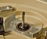
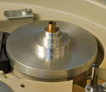


-- Later Version......Below: shots of the later design: In this version the shaft is fixed solid within the stepped pulley while the bushings and ball thrust are found within the cast chassis. This was used in both mk1 and mk2 designs. The earliest serial number I've seen here with the later stepped pulley bearing is 27520...so far. Of course, the TD124 mkII had this version stepped pulley.
 chassis sn 27520
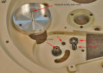 chassis sn 33389
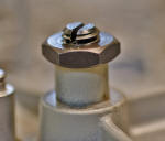 chassis sn 57175. Note: Stepped pulley height adjustment is made by
first loosening the hexagonal lock nut, then turning the slotted stud
with a flat blade screw driver to lower or raise it. Then tighten
lock nut. Noting that cast material is aluminum and fastener
material is steel.
chassis sn 57175. Note: Stepped pulley height adjustment is made by
first loosening the hexagonal lock nut, then turning the slotted stud
with a flat blade screw driver to lower or raise it. Then tighten
lock nut. Noting that cast material is aluminum and fastener
material is steel.-- Points of Lubrication:
-- It should be noted that the lubes we use for this turntable need to be compatible with yellow metals, and in particular with porous bronze bushings. Any additive that might clog the porosity of these bushings can cause wear where it normally would not happen. IE. avoid any lube that contains teflon flakes, for instance. These can clog the porosity of Oilite bushings. That said, I have not included any comments regarding any modern synthetic lubes but I do maintain that we are looking for a general purpose circulating oil/turbine oil.
-- From the owner's and service manuals:
-- ( motor) use Texaco Regal Oil B (ROB)
-- (spindle bearing): use Caltex or Texaco Regal Oil B (ROB)
-- (idler wheel) Regal Oil G (ROG) oil on top of the bushing, between the stop ring and the wheel.
-- (stepped pulley) Regal Oil G (ROG)
-- https://www.lubefinder.com/range/texaco-regal-oil.html
-- Above link: explains viscosity of the two oil types recommended by Thorens
-- Viscosity ROB - 20 wt SAE
-- Viscosity ROG = 50 wt SAE (note that gear lube with a rating of 90 wt SAE is comparable in viscosity to the ROG)
-- Btw, gear lube viscosity is rated differently from regular circulating oil viscosities. So,..... a 90 wt. gear lube has approximately the viscosity of 50 wt. circulating lube. Not sure why this is. I'm no chemical engineer. But --- the properties of gear lube, I presume, have to do with certain aspects of lube performance regarding the meshing of spiral bevel gear trains as are found in automotive differentials. ROG is not the same as gear lube. Certain of it's properties will be different.
For a modern day equivalent to the lubes recommended by Thorens back then, see Texaco R&O 46 ISO. (ISO 46 converts to 20wt SAE). For the ROG see Texaco R&O 220 (ISO 220 converts to 50wt SAE)
-- While the two recommended lubes are not available in small volumes at your local hardware or auto parts store a useful equivalent to the ROB oil can be found in a 3 fl. oz can from the 3-IN-One company. No, not 3-IN-ONE oil. That's too thin. We want the 3-IN-ONE MOTOR OIL (20wt SAE)
-
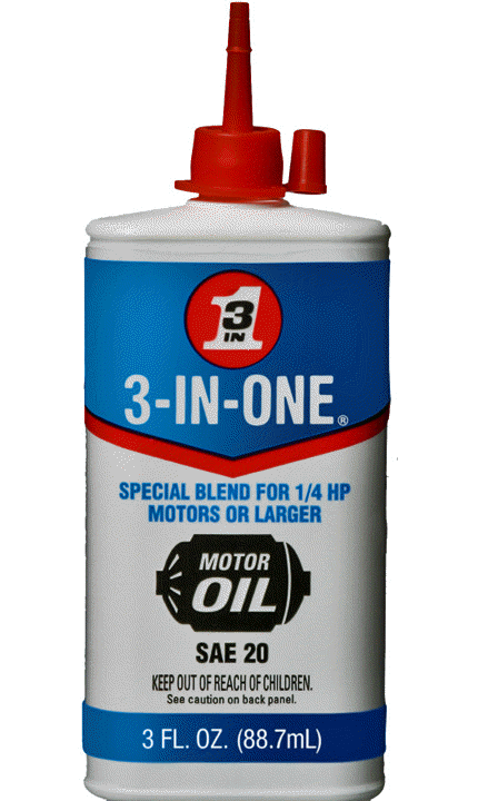
-- Use this as a substitute for the Texaco ROB. Available at your local hardware store. I've found mine at the Ace Hardware chain here in the Pacific North West.
For an ROG substitute I am making no recommendation at this point but -- fwiw -- I am experimenting with various gear lubes in the SAE 90wt range. For use at the Stepped pulley and the idler wheel axle.
____________________________________________________________horizontal rule
-- Notes on the magnetic attraction between the iron platter of the TD124 and certain moving coil cartridges.
I've found that there is a measurable magnetic pull* between the iron flywheel below and the cartridge above it. The only thing that can reduce this magnetic attraction is distance. And there isn't enough distance when using certain cartridges. This magnetic attraction between cartridge and flywheel can potentially mislead us when setting vertical tracking force of the arm/cartridge.
Below I offer a means to measure the strength of magnetic pull while using a DL-103R moving coil phono cartridge.
* The iron flywheel below does indeed attract cartridges fitted with stronger magnets. Typically moving coil cartridges will have a magnet within that is strong enough to attract itself toward the iron flywheel of the TD124.


 Scale: Micro-Tech VTF gage.
-- Above three photos illustrate one method of determining just how much magnetic pull there is with any given cartridge. Left photo; a digital scale with a means of measuring vertical force at record level. This scale is designed to be used while sitting directly on the platter mat.* Middle photo; taking a reading with the cartridge away from the iron platter below. Right photo; taking a reading with the cartridge in the area that is over the iron platter beneath. Difference between over iron and away from iron; 1/2 gram!
*(But not while sitting on a record. That would increase the vertical distance by the thickness of the record. If you did that your measurement wouldn't be as accurate as it is with the scale sitting directly on the mat.)
The solution to the magnetic pull problem was to set VTF using this particular scale directly over the platter mat and above the iron flywheel beneath. The magnetic pull is still there, but it will remain constant to your setting while the record plays. And now we know we are not putting too much force on the suspension of the DL-103R. Btw, too much tracking force can result in a hard to diagnose distortion.
-- back to the Thorens Dept.
