-edible zone-
Thrust Balls:
2/2/2014
Does it make sense to try
different materials and grades of the bearing ball in the thrust end of
the platter bearing? Let's see if we can't prove it one way or another.
Ceramic: 9/32" SiN4 Ceramic grade 5 (sourced from Boca Bearing
Company)
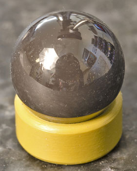 Prior to assembly, the ceramic ball is perched in the cup end of the
thrust cap that will be used. Looking close, the ball has a highly
polished finish. And also tiny bits of dust clinging tenaciously to its
outer surface. I wiped the ball with a chamoise several times to no
effect.
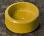 Looking at the interior of a freshly made Torlon 4203 thrust cap.
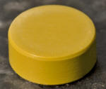 Exterior detail. The Torlon 4203 cuts fairly clean with commonly used
lathe tool bits of carbide and high speed steel. A hand held metal file
was used to apply edge breaks while the part was turning in the lathe.
The part was cut complete in a single setup. Turning the OD. Facing off
the open end. Drilling with a center drill to open up for the boring
bar, which was used to cut the ID for size and also used to cut the
interior face to depth. To establish the length of the part, a parting
off tool was used. To finish it, a secondary operation was applied using
a bench lap to lap the thrust face of this part into a smooth condition.
This process has been used on all of the above thrust caps, including
this one.
Assembly.
Replacing the plastic thrust cap at the tip end of the bearing
shaft is somewhat simpler than replacing the bearing ball. For the cap
all one needs to do is leave the player upright and disassemble the
platter from the motor unit, then remove another 'gazillion' machine
screws an assortment of keepers and cover plates......and a platter
brake assembly. After than we can gingerly lift the rotor, the very
valuable rotor, up out of its bearing housing. To understate it,
Technics has their player securely buttoned up and held together tight.
But to remove the bearing ball at the bottom of the bearing
housing, one needs to hold the motor unit upside down safely and
securely, then unscrew another gazillion machine screws to remove the
bottom cover. Having done that it exposes the main-board circuitry and
the all important platter bearing thrust cup sticking up in the middle
of it all. But one needs be careful not to disturb the printed circuit
boards and the small city of electronics parts attached to them. Or
perhaps it is better to remove the printed circuit board prior to
removing the bottom bearing thrust cup. The parts on this player are
rare and valuable. See elsewhere in this article ( Disassembly photos )
for some details on removing the platter bearing thrust cup. It is held
on by threads and a generous amount of thread sealer. Care needs be
taken. Care and technique...if you want to avoid damage.
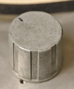 The bottom thrust cap, removed. Note this area checks very flat and also
parallel with interior faces.
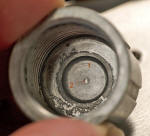 Looking into the thrust cup. Notice the threads, the spot face at its
bottom and the prominent crater that indicates previous use. The bearing
ball holds a fixed position, does not turn and is held in firm contact
with both this cap and the side walls of the bearing housing where it
resides. click the photo to view it full size. Then notice two bits of
annotation. A number 1, indicating the spot face surface, and a number
2, indicating a wear spot where the bearing ball makes firm contact with
the cup.
Let's measure the wear spot for depth.
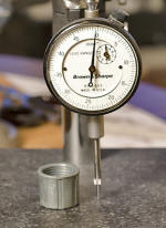
A granite based drop indicator is used to measure the wall thickness at the cup bottom. This shot shows the indicator almost set to zero. This was adjusted prior to making measurements to exact zero on the big dial. Also take note of the smaller dial within the face of the indicator. It is also set to zero. That smaller dial counts revolutions of the large needle. One rev is .050 inches.
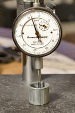 Checking the spot face area for thickness. What's the reading? Reading
the two dials I get .096 inches of wall thickness between cup bottom and
the granite.
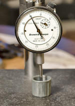 Checking in the center of the wear crater. What's the reading? Look at
it two ways. Compare this reading to the previous reading taken on the
spot face surface to get a simple depth read. Just subtract the smaller
value (crater read) from the larger value (spot face read) to find depth
of the crater. I get just a touch over .001" of depth in that crater.
Not very deep. You can also figure wall thickness at the crater bottom
simply by reading the dials. For that I get .095 inches. Isn't this fun.
While I've got the thing apart let's take a look at some other sizes.
 I'm using a Mahr gage to find ID size of the bearing housing. I used the
Mahr gage to scan up down and around within this housing. The gage
indicates a straight through bearing bore with no relief areas, that is
straight and round. Variation of the readings was less than .0002
inches.
 Using a micrometer I'm gaging the diameter of the original equipment
thrust bearing ball. Guess what; the .2815 inch ball is closely size for
size with the bearing housing inside diameter. This also works out to a
fractional inch size; 9/32". Go figure. A Japanese manufacturer, where
the metric system dominates, choses a 9/32 inch bearing size for their
top of the line record player. What this leaves us with is a bearing
ball that is size for size with the bearing housing it must fit into. A
small amount of force is used to assemble and disassemble the ball from
the housing each time. That way the ball is not allowed to move, not
even slightly, while doing its job at the bottom of the platter bearing.
 Checking the new SiN4 Ceramic grade 5 bearing ball. Funny, it checks
.0013 inches larger in diameter than the oem ball. And this is over the
nominal 9/32" stated size for this bearing. What it means is that if I
use this bearing ball it will need to be pressed into the bottom end of
the bearing housing. Should I do that or should I find another ball? As
it turned out I just placed the ceramic ball on the opening end of the
bearing housing, then screwed the bottom cup down over it to press the
ball into position. The required force did not seem excessive to my
calibrated wrist as I wrenched the threaded cup down over its fitting.
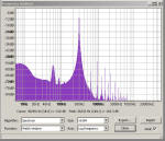
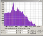
Test Record Plots for the ceramic ball:
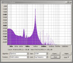
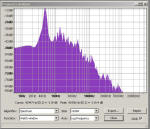
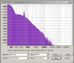
As I review this group of test plots and compare against previous plots from the different materials while using the oem bearing ball, I see that there are some small differences in the measurements. In particular as I look at the silent groove plot exclusively I can find differences between them on the order of 2 to 3 db. And that is all. This is not significant.
After 1 week: 2/9/2014
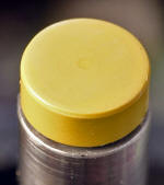 after 1 week. Wear spot measures Ø.030 using a 10x magnifier with
reticle.
Wear rate does not stand apart from the previous group
when using the standard issue hardened steel bearing ball.
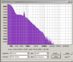
Test
record spectrum plots after one week
Listening notes:
I heard no overt differences in this
configuration than I had previously. Perhaps, there were some subtleties
to be appreciated. Inner details seem nicely rendered. I can't say that
I did not notice this in any of the other cap/ball configurations.
Nonetheless, sound quality is as good as I have heard it over the
duration of this bearing cap/ball test session. As good as I've yet to
hear out of this motor unit regardless of configuration.
