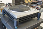
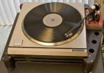
-edible zone-
At first I wanted to name this plinth
design the "Test Mule". But a suggestion from a friend sounds better.
From here on I name this plinth style "the mule". I like that this name
echos an Azimov character from the Foundation series of novels. The
Mule.
The Mule Plinth
Having already taken dimensional
measurements on the bearing spindle shaft, the bushing bore and a visual
exam of the thrust, we know that bearing wear is minimal, except that
the thrust pad is in need of renewal. For this part of the project, the
deck has been re-assembled. The bearing, spindle and bushing has been
gently cleaned and then reassembled with fresh 20 wt turbine oil for
lube.
The next step is to make a test mule to study and measure
the performance of this machine. Specifically, the goal is to get points
of reference for rumble and wow/flutter performance. This data will help
to determine the electrical/mechanical condition of the motor unit. If
there is significant wow/flutter, it will point toward problems with the
controller electronics. If significant rumble is reported, it will point
to excessive wear at the platter bearing. But I've already taken early
listening sessions with this deck and know that the unit reproduces
music quite well and with no audible evidence of low frequency rumble.
Like all my plinth designs, it starts out as a sketch, then, once I
have a rough outline of the shape, I refine the shape in my 3D cad
software of choice, Rhino3D.
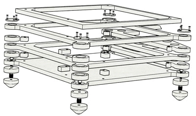
This "test mule" plinth is intentionally light. The idea is to produce a method of supporting the motor unit and tonearm together in a single structure. But this structure needs to be one that does not depend on high mass to dampen whatever mechanical vibrations the motor unit may produce. Rather, I want to be able to readily measure for rumble and wow/flutter without having to consider that the plinth may be masking some of the mechanical noise. However the design does provide a hollow chamber in each of the 4 vertical cylindrical supports to hold a volume of #9 lead shot as a means to dampen the plinth at its support point. This idea is to help "plant" each cone foot solidly onto the support surface.
The plinth needs to be a rigid structure, yet, not at all massive. An experiment.

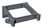
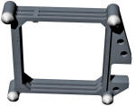 This build will be a stacked layer baltic birch multi-ply glue-up.
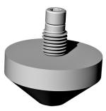 3d cad quick shade. In this photo self tapping machine screw inserts
will tap into the wood of the plinth, then accept the 1/4-20 threads of
the allen bolt, which screws into and holds the Stillpoint cones. The
advantage to this arrangement is that there is a slight range of
vertical adjustment at each cone which can be used to level and
stabilize the deck.
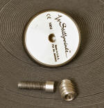
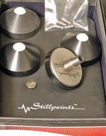 Earlier this year I purchased a used set of Stillpoints cone feet for
this project. These cones are well regarded by many audiophiles in the
know. However the manufacturer has replaced this model with another that
claims to be an improvement. The advantage for me is that I can now
purchase this old technology at 2nd hand rates, while more affluent
audiophiles upgrade their equipment with the newer Stillpoint cones that
are significantly more expensive. Progress is good.
________________________________________________________________horizontal rule
Next step....................build the actual thing.
10/27/2013

 (click thumbnail for full size image)
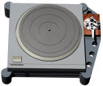
Above: Just prior to mounting and aligning the tonearm.
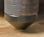 The Stillpoint cones connect via 1/4-20 threaded studs to the thread
inserts that have been installed within the Test Mule plinth. This
method allows height adjustment at each of the 4 cone footers for
leveling. (editor's note: 08-29-2023, No adjustments were needed
on the surfaces the Mule stood over.)
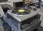
In rough and setup for an early audition.
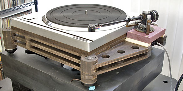
 A few details not yet done, such as finish but need to fab four shot
chamber caps. Note the two dowel pin holes on either side of shot
chamber.
After finish pics:


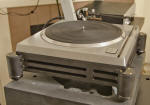
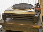
Finish coating: highly textured black enamel. Prior to paint, three successive coats of sanding sealer. Sanded between coats. Then 3 coats of the textured black with sanding between those coats.
_____________________________________________________________________________________horizontal rule
11-08-2013
But next I changed the pile-up method on top of the Minus-K.
The TD124 slate plinth slabs were removed and replaced with an 18 x 18 x
3 inch granite inspection plate. On top of the granite is a Neuance
platform. The Neuance platform will interface with the ceramic cone feet
under the Mule plinth and should serve to dampen vibes coming off the
sp10. (editor's note; 08-29-2023, none of that verified by any test)
As noted in my review of the Minus-K isolation platform, there is a
minimum(90 lbs) and a maximum (155 lbs) weight load requirement. That is
why when I removed the TD124 slate plinths I had to replace those with
something of similar weight. In this case the Granite is actually
heavier than the horens' slate. The granite by itself weighs 108 lbs.
The Mule with SP10mkII weighs 31 lbs. combined weight is then 139 lbs
standing on the Minus-K. And, thusly, the Minus-K happily floats the
sp10 in its Mule.
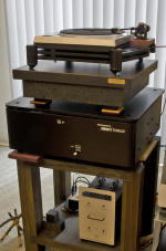 Long view detail of the pile-up. The heavy and rigid stand is just a
tiny bit undersized for the Minus-K..... Nevertheless, it is adequate
for supporting the weight load it carries.
Some brief, subjective listening observations on how this
setup sounds:
Fast. Very musical. Dynamic. Great bass. A very
good sense of energetic drive. Better this way than when I had it in the
earlier plinth. Detailed but not really analytical sounding. Nice.
