-edible zone-
1)
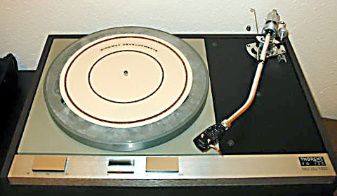
above photo #1: Ringmat 330 mkII on a Thorens TD125LB.
2)
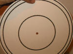 (click thumbnail for full size image)
Above photo #2: Bottom side of Ringmat. Notice that the outer two rings are spaced to straddle the ring on the opposite side. When the record is placed on top, the weight load will stretch the paper between the upper and lower rings creating a suspension.
3) What happened to #3?
4)
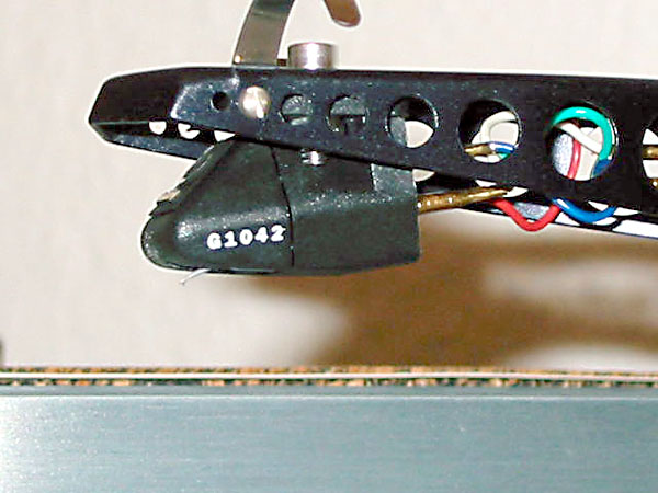
Above photo #4: Side view of the Ringmat shows paper substrate
sandwiched between upper and lower cork rings.
Thanks to Serge
Roch for these pictures of his Thorens and Ringmat. Very useful.
The Ringmat Patent
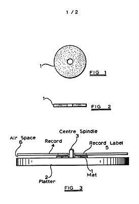 Patent drawings, figures 1,2 and 3
 Patent
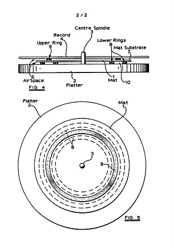
drawings, figures 4 and 5.
RECORD PLAYER MATS
Patent Number: GB2256303
Publication
date: 1992-12-02
Inventor(s): ROGERS JOHN DAVID MICHAEL;
MORECROFT DENIS NEIL
Applicant(s): ROGERS JOHN DAVID MICHAEL
(GB); MORECROFT DENIS NEIL (GB)
Requested Patent: GB2256303
Application Number: GB19920009953 19920508
Priority
Number(s): GB19910010058 19910509
IPC Classification: G11B3/61
EC Classification: G11B19/20A1
Abstract
A record player mat 1 for supporting a record 4 on the platter 2 of a
record player is adapted to support the record 4 such that a substantial
proportion of the playing area of the underside of the record 4 is not
in contact with the mat 1 so that noise energy in the record 4 is
dissipated in the air space 6 between the record 4 and the platter 2.
The mat, which may be made from paper, cardboard, felt, leather, cork,
rubberised cork or plastics, may be disc shaped, and have one or more
ring shaped support members on each side thereof.
Data supplied
from the esp@cenet database - l2
Description
RECORD PLAYER MATS
This invention relates to record player mats
and to record players incorporating such mats. It relates more
especially to record player mats for supporting, e.g. a vinyl record on
the platter or turntable of a record player.
There are currently
two schools of thought on the subject of the ideal record support for
accurate replay of the vinyl record used in an audio system. Both
endeavour to overcome the vibration problems caused by unwanted energy
from both the tracing stylus and the sound pressure waves in the room.
This unwanted energy causes the stylus to move in a way which is
unrelated to the original signal and the accuracy of reproduction is
reduced. On method is to try to simulate the conditions in which the
record was originally cut by clamping the record to a solid, heavy
surface which will hold it still, prevent any movement and therefore
allow perfect reproduction of the information in the record grooves.
Another method is to allow movement to occur but to try and arrange that
it is as inaudible as possible.
The first method is not ideal
because it is extremely difficult to stop vibration energy in any
material. In practice the energy will always be changed in form or
reflected back into the system from which it originated. The second
method is more practical but it has not yet been properly designed in a
total system approach.
It is an object of the present invention
to provide an improved form of record player mat which can be used in
conventional record players or as part of a total system approach and
which enables the affects of unwanted vibration energy to be reduced.
According to one aspect of the present invention there is provided a
record player mat for supporting a record when positioned thereon, said
mat being adapted to support said record such that a substantial
proportion of the playing area of the side of the record which is in
contact with said mat is not in contact with said mat.
In one
preferred arrangement for carrying out the said one aspect of the
invention, it is arranged that the mat is of disc shaped form adapted to
support said record in a central portion thereof, whereby the outer
portion of said record which includes a substantial proportion of said
playing area is not in contact with said mat.
In another
preferred arrangement for carrying out the said one aspect of the
invention, it is arranged that the mat comprises a disc shaped substrate
having a ring shaped support member thereon for supporting the record.
It may be arranged that said disc shaped substrate has a ring shaped
support member on each side thereof, and more preferably said disc
shaped substrate has a pair of spaced apart ring shaped support members
on an underside thereof, the ring shaped support member on the top side
thereof overlying the space between said pair of spaced apart ring
shaped members.
It may conveniently be arranged that said disc
shaped substrate has two pairs of spaced apart ring shaped support
members on the underside thereof and two ring shaped support members on
the top side thereof, one of said two ring shaped support members
overlying the space between one of said two pairs of spaced apart ring
shaped support members and the other of said two ring shaped support
members overlying the space between the other of the said two pairs of
spaced apart ring shaped support members.
It may be arranged that
the disc shaped mat is fabricated from felt, leather, cork, rubberised
cork, cloth, plastics or any other suitable material, and may be of air
or fluid filled form.
It may be arranged that the disc shaped
substrate is fabricated from paper, cardboard, felt, leather, cork,
rubberised cork, plastics or other suitable material, and said ring
shaped support member or members may be fabricated of rubberised cork,
plastics or other suitable material.
In accordance with another
aspect of the present invention there is provided a record player
comprising a platter or turntable adapted to receive a record to be
played and a mat in accordance with said one aspect of the present
invention provided on said platter or turntable for supporting said
record.
In accordance with yet another aspect of the present
invention there is provided a method of supporting a record to be played
in which a mat or other support is provided on which the record is
positioned such that a substantial proportion of the playing area of the
side of the record which is in contact with said mat or other support is
not in contact therewith.
Some exemplary embodiments of the
invention will now be described reference being made to the accompanying
drawings, in which:
Figs. 1 and 2 are plan and side views
respectively of a record player mat in accordance with a first
embodiment of the present invention;
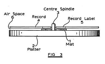
Fig. 3 is a diagrammatic
side view illustrating the record player mat of Figs. 1 and 2 supporting
a record on a record player platter;
Fig. 4 is a diagrammatic
side view illustrating a record player mat in accordance with a second
embodiment of the invention supporting a record on a record player
platter; and
Fig. 5 is a plan view of the arrangement of Fig. 4
with the record removed.
The embodiments of the invention to be
described are based on the realisation that a record to be played, e.g.
a vinyl disc, must be supported in a manner which allows movement but
the majority of the movement must be outside the audio band. The
movement that occurs should be as free as possible from structural
resonances within the record material or anything attached to it
including its support mat. The record support mat must generate the
minimum noise whilst absorbing the movement and dissipating the unwanted
energy. Existing mats offer various degrees of energy absorption but
they also generate substantial amounts of noise close to the tracing
stylus.It has now been appreciated that since normal vinyl records are
stiff enough to be self-supporting, it is possible to provide a record
support mat which supports the record but which allows all or at least a
very substantial part of the playing area i.e. the grooved part, of the
record to be clear of the mat i.e.
adjacent an air space so that
any noise energy in the record is dissipated in the air which is in
contact with the record.
In the embodiment of the invention
depicted in
Figs. 1 to 3 of the drawings, a record player mat 1
is of disc shaped form having an area which substantially corresponds to
the label area of a normal 12 inch record e.g. typically of 10 cm.
diameter, and having a thickness of typically 3 mm.
As depicted
in Fig. 3, the record player mat 1 is positioned on the turntable or
platter 2 of a record player with the centre spindle 3 thereof extending
centrally through it, and a vinyl record 4 is positioned on and
supported by the mat 1. The size of the mat 1 is arranged to
substantially correspond to that of the record label 5.so that a very
substantial part of the playing area e.g. the grooved area of the
underside of the record 4, i.e. the side in contact with the mat 1, is
not in contact with the mat 1 so that an air space 6 is provided between
the record 4 and the top surface of the platter 2.
The thickness
of the mat 1 is conveniently arranged such that the record 4 is at the
same height relative to the platter 2 had a conventional mat been used
and the material of the mat 1 is chosen so as to be lossy in
transmitting vibrational energy and quiet when in contact with a
vibrating surface. As has already been mentioned, the provision of the
air space 6 in the vicinity of the playing area of the record 4 allows
any noise energy in the record 4 to be dissipated in the air adjacent
the record 4. Typically the material of the mat may be felt in any
suitable grade, soft leather, soft cork, rubberised cork, suitable cloth
materials, plastics or other suitable material.
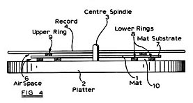
In Figs. 4 and 5
of the drawings there is depicted an alternative construction of record
player mat 1.
The mat 1 of Figs. 4 and 5 comprises a disc shaped
substrate 7 having on the underside thereof a pair of concentrically
spaced apart lower supporting rings 8 and on the upper side thereof a
single supporting ring 9, the upper supporting ring 9 being located so
that it overlies the space 10 between the lower supporting rings 8.
As depicted in Fig. 4, the mat 1 is positioned on the platter 2 of a
record player with the lower supporting rings 8 in contact with the top
surface thereof and the record 4 is positioned on the mat 1 so that it
is supported on the upper supporting ring 9.
In this way an air
space 6 is provided both between the record 4 and the substrate 7 of the
mat 1 and between the substrate 7 and the top surface of the platter 2.
In practice the upper ring 9 would be arranged so that it contacted
part of the playing surface of the underside of the record 4, but it is
dimensioned such that a very substantial part of the playing area of the
record 4 is not in contact with the mat 1. Thus noise energy in the
record 4 can be dissipated in the air space 6 as in the embodiment of
Figs. 1 to 3. In addition, it is found that the disposition of the upper
ring 9 and the lower rings 8 on the substrate 7 of the mat 1 causes
unwanted energy in the record 4 to produce a rippling effect in the
substrate 7 of the mat 1 which dissipates the unwanted energy without
moving the record significantly from the point of view of the tracing
stylus (not shown) of the record player.
The record player mat 1
of Figs. 4 and 5 operates by absorbing energy from the record 4 whilst
minimising record movement. Normally the record 4, which vibrates as a
result of input of energy from the tracing stylus (not shown), will move
in its resonant modes and the movement causes extra stylus deflection
which is error information. The mat 1 provides an impedance match
transferring the unwanted vibration energy into its own structure and
dissipates the energy into the air space 6 underneath the record 4. The
dimensions and the material of the mat 1 may be chosen to suit any
particular application. Materials such as paper, cardboard, felt,
leather, cork, rubberised cork, plastics or other suitable material may
be used for the substrate 7 and rubberised cork, plastics or other
suitable material may be used for the supporting rings 8 and 9.
In some arrangements it may be advantageous to provide a record player
mat 1 which comprises two or more pairs of lower supporting rings 8 and
corresponding upper supporting rings 9, in order to provide additional
support for the record 4 whilst still maintaining a substantial
proportion of the playing area of the record free of contact with the
mat 1.
Also, although the configuration of two lower supporting
rings 8 and one upper supporting ring 9 is to be preferred, other ring
configurations could be used.
The method of energy absorption in
the mat 1 of
Figs. 4 and 5 distinguishes it from conventional
record supports in that it does not introduce noise onto the underside
of the record during operation. Harder conventional mats fail to absorb
the energy in the record and allow reflected energy to dominate the
replay surface. Felt mats generate noise in the record. The concept of
minimal contact area allows the mat 1 to move to dissipate vibration
energy without moving the record.
Although in the embodiments
which have been described a mat separate from the platter has been
proposed, it is envisaged that a platter may be provided effectively
with a built-in mat, i.e. with a top surface which replicates at least
to some extent the characteristics of a mat as described, thereby making
the provision of a separate mat unnecessary.
Data supplied from
the esp@cenet database - l2
CLAIMS
1. A record.
player mat for supporting a record when positioned thereon, said mat
being adapted to support said record such that a substantial proportion
of the playing area of the side of the record which is in contact with
said mat is not in contact with said mat.
2. A mat as claimed in
claim 1, which is of disc shaped form adapted to support said record in
a central portion thereof, whereby the outer portion of said record
which includes a substantial proportion of said playing area is not in
contact with said mat.
3. A mat as claimed in claim 1, comprising
a disc shaped substrate having a ring shaped support member thereon for
supporting said record.
4. A mat as claimed in claim 3, in which
said disc shaped substrate has a ring shaped support member on each side
thereof.
5. A mat a-s claimed in claim 4, in which said disc
shaped substrate has a pair of spaced apart ring shaped support members
on an underside thereof, the ring shaped support member on the top side
thereof overlying the space between said pair of spaced apart ring
shaped members.
6. A mat as claimed in claim 5, in which said
disc shaped substrate has two pairs of spaced apart ring shaped support
members on the underside thereof, and two ring shaped support members on
the top side thereof, one of said two ring shaped support members
overlying the space between one of said two pairs of spaced apart ring
shaped support members and the other of said two ring shaped support
members overlying the space between the other of the said two pairs of
spaced apart ring shaped support members.
7. A mat as claimed in
claim 1 or claim 2, fabricated from felt, leather, cork, rubberised
cork, cloth or plastics material.
8. A mat as claimed in claim 1
or claim 2, of air or fluid filled form.
9. A mat as claimed in
any of claims 3 to 6, in which said disc shaped substrate is fabricated
from paper, cardboard, felt, leather, cork, rubberised cork or plastics
material.
10. A mat as claimed in any of claims 3 to 6 or 9, in
which said ring shaped support member or members are fabricated of
rubberised cork or plastics material.
11. A mat substantially as
hereinbefore described with reference to the accompanying drawings.
12. A record player comprising a platter or turntable adapted to
receive a record to be played, and a mat as claimed in any preceding
claim provided on said platter or turntable for supporting said record.
13. A method of supporting a record to be played, in which a mat or
other support is provided on which the record is positioned such that a
substantial proportion of the playing area of the side of the record
which is in contact with said mat or other support is not in contact
therewith.
Amendments to the claims have been filed as follows
1. A record. player mat for supporting a record on the platter of a
record player, said mat comprising a disc shaped substrate having a ring
shaped support member on each side thereof for contacting the record and
the platter respectively, whereby in use an air space is provided
between said substrate and the record and between said substrate and the
platter over a substantial proportion of the substrate area.
2. A
mat as claimed in claim 1, in which said disc shaped substrate has a
pair of spaced apart ring shaped support members on an underside
thereof, the ring shaped support member on the top side thereof
overlying the space between said pair of spaced apart ring shaped
members.
3. A mat as claimed in claim 2, in which the ring shaped
support member on the top side of said substrate overlies only part of
the space between the pair of spaced apart ring shaped support members
on the underside of said substrate.
4. A mat as claimed in claim
2 or claim 3, in which said disc shaped substrate has two pairs of
spaced apart ring shaped support members on the underside thereof, and
two ring shaped support members on the top side thereof, one of said two
ring shaped support members overlying the space between one of said two
pairs of spaced apart ring shaped support members and the other of said
two ring shaped support members overlying the space between the other of
the said two pairs of spaced apart ring shaped support members.
5. A mat as claimed in any preceding claim, in which said disc shaped
substrate is fabricated from paper, cardboard, felt, leather, cork,
rubberised cork or plastics material.
6. A mat as claimed in any
preceding claim, in which said ring shaped support members are
fabricated of rubberised cork or plastics material.
7. A mat
substantially as hereinbefore described with reference to Figs. 4 and 5
of the accompanying drawings.
8. A record player comprising a
platter or turntable adapted to receive a record to be played, and a mat
as claimed in any preceding claim provided on said platter or turntable
for supporting said record.
Data supplied from the esp@cenet
database - l2
